- Home Old school pinball<1985
- Grand Prix (EM) 1976
- Firepower (SS) 1980
- Space Mission (EM)1976
- Genie (SS) 1979
- Magic Castle (SS) 1984
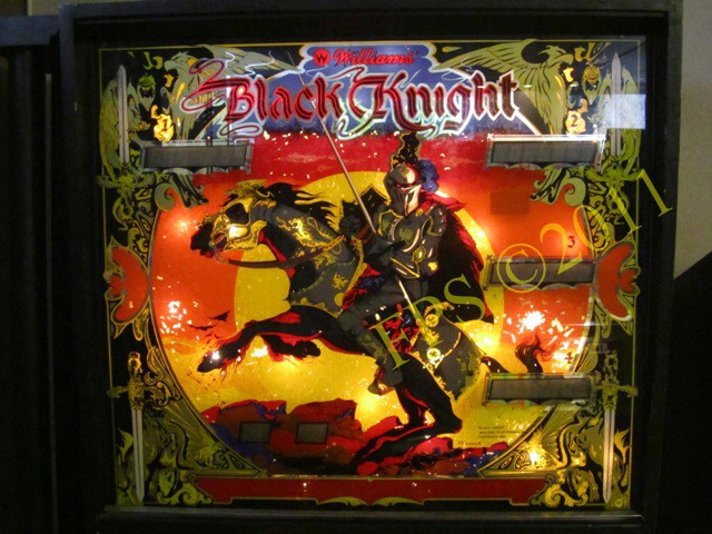
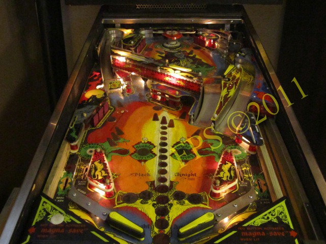
- Black Knight (SS) 1980 New school pinball >1985
- High Speed (Sys11) 1986
- Earthshaker (Sys11) 1989
- CFTBL (WPC) 1992 Arkad Projekt
- JK-Kabinett med MAME Contents Black Knight
- Playfield Refurbishing
- Playfield Painting
- Cabinet Refurbishing
- Electronics
- Before-After Pictures
- Refurbishing Diary
- Finished project
- Dokument - Flyer
|
Language |
|
|
Williams Black Knight SS Refurbishing project - Part IV!
There where some electronic issues on mine Williams Black Knight 1980 and here I will try to describe the work.
FIRST...
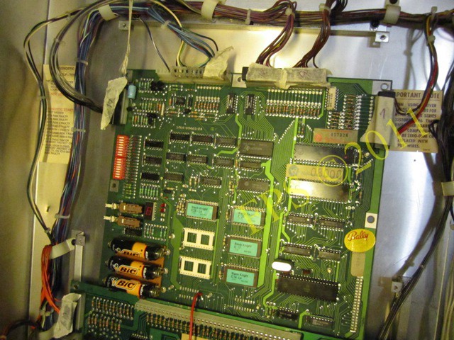
Williams Black Knight use a Motorola 6802 chip for MPU and is named Williams System 7 and the memory capacity is rather large with 512 byte RAM. Settings and high score is stored in a CMOS RAM memory. PIA chips 6820 or 6821 together with different transistors are used to drive solenoids, lamps, switches and displays.
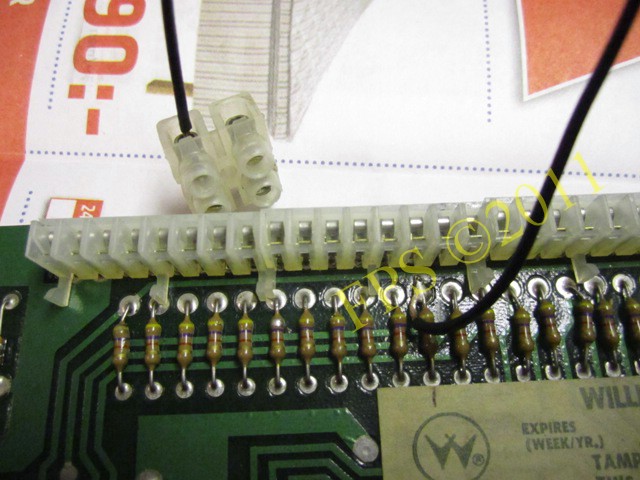
Problems on this old machines can often be referred to the connectors. This old version of Molex connectors is situated on the PCB Boards. On the PCB boards the male connector is to be found and the female housing connector is connected to this male connector. All distribution between the boards and for example the playfield is going through this connectors.
There is a type of connector that consist of several Molex connectors in a row and this connector is called 40 pin Inter-board connector - this 40 pin Inter-board connector distribute the signals between the CPU board and the driver board. Williams worked out this solution to easier separate the boards for maintenance at the operator. Unfortunately this connectors will not be stable after many years of use and many problems can be related to this 40 pins story - mention that the signals for the data bus and the address bus runs through this 40 pin Inter-board Connector. Electronic problems is often related to this connectors as broken pins or cracked solder joints. It is important that the connectors is clean and solid because of the high speed signals, otherwise strange behavior can occur during game play.
THEN...
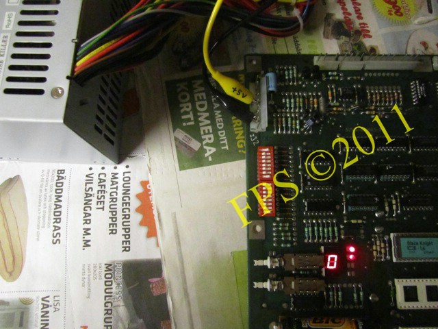
When you turn on power to mine Williams Black Knight it would not go to Attract mode (all lamps on the playfield flashes and it is ready to start a game). None of the displays show any numbers and it may be due to an IC circuit (display PIA) that is defect on the motherboard (MPU board). The only thing that works is the lamps in the playfield and lamps behind the backglass in the top box (General Illumination). The sound card has no problem since it emits all sounds when you press the test button. There is a simple numeric display on the motherboard (MPU board) which after self control of the board shows different error codes, in my case shows a "0" indicating that the CPU is probably locked and will not start.
There are various reasons for CPU to lock up and a few reasons of many may be,
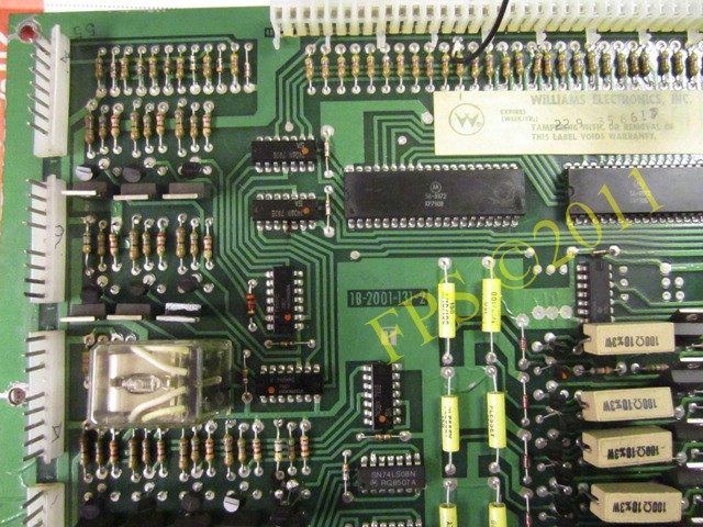
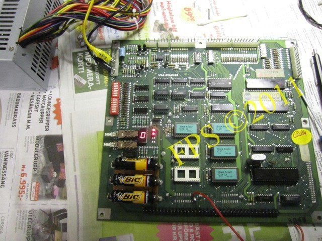
CPU AND DRIVER BOARD IN BACKBOX
Above the MPU board, it is mounted on a metal L-frame with screws.
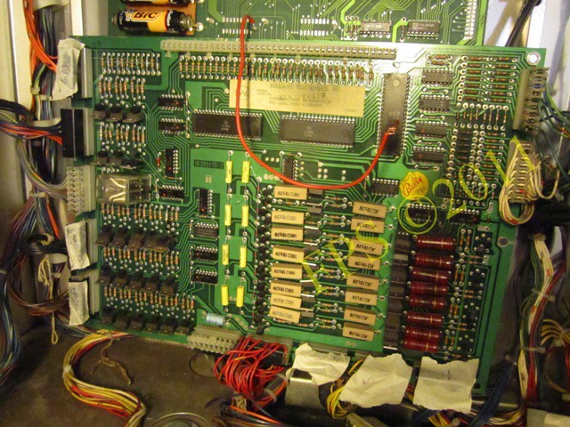
Above we can see the driver board, between the boards is the infamous 40-pin Inter-board connector and a mandatory fix is to replace this connector to achieve a stable operation of the pinball machine, see further mine Williams Firepower 1980 project.
TEST OF OPERATION
Before turning on power to the pinball machine for the first time you should make sure that all fuses have correct value (A). Sometimes a previous owner put in a fuse with too high amps and this can result in damage to the circuit board or other components of the pinball machine.
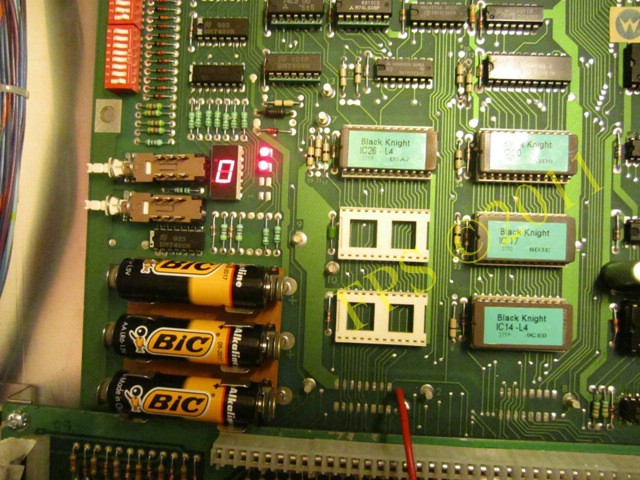
The picture shows the numeric display on the motherboard (MPU board) which after self control of the board shows different error codes, in my case shows a "0" indicating that the CPU is locked up.
General illumination behind backglass lights without problem.
General illumination on playfield lights without problem but no CPU controlled lamps flashing in the playfield.
INSPECTION OF THE BOARDS
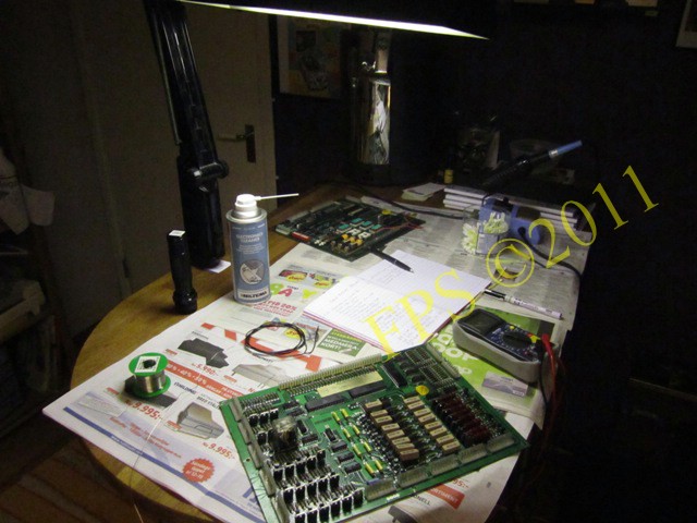
Now it is time to pick out the circuit boards from the backbox and make a visual inspection and try to see if there are any obvious defects on the circuit boards that can be repaired.
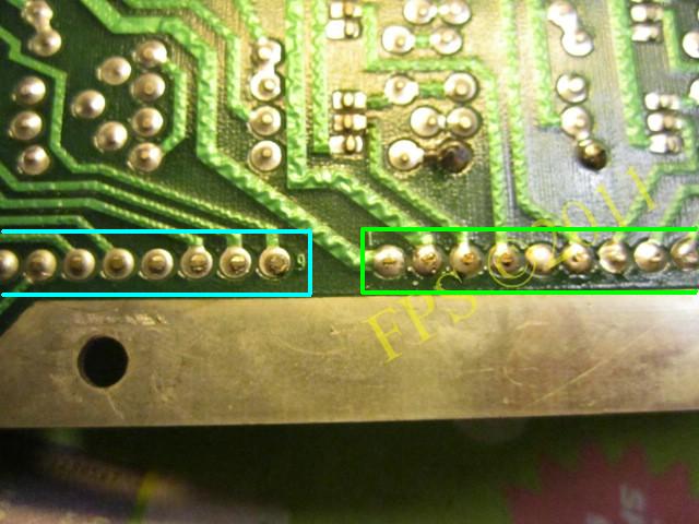
To ensure that there are no cracked solders joints on the back of the connectors on the circuit boards I reflow the solder and add some new solder as well. The solder joints that are visible to the right in the picture are reflowed with new solder, highlighted in green.
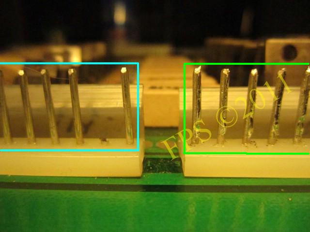
A thin layer of solder are added to the contact pins to increase its conductivity and cause them to become thicker. The reason for this is to make as good contact as possible with female pins that can sometimes be stretched after repeated been unconnected.
A resistor R42 (68 Ohm 10% 1/2W) is changed by a previous owner and a continuity measurement with the multimeter is made to ensure that the resistor legs have good contact with the copper paths on the back of the circuit board and its resistance is measured.
IC2 (N7408) used to operate the solenoids 5-8 is replaced and I check so that it has good contact from all the legs to the copper paths (foils) on the circuit board.
Also find that transistor Q8 (TIP122 NPN - Darlington) is replaced.
Although the transistor Q22 and Q24 (2N4401 NPN) is previously replaced.
 |
 |
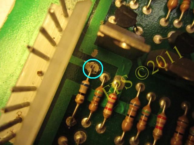
In the pictured to the left we see a bad solder joint for a transistor, it is reflowed with solder to become adequate.
The picture shows a part of the 40-pin Inter-board connector, and we see that it already has been replaced with a newer version of a previous owner but they have managed to destroy a solder ear on the back of the circuit board, hence the red wire that has served as a bridge between the MPU board and the driver board.
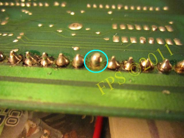
The broken solder ear.
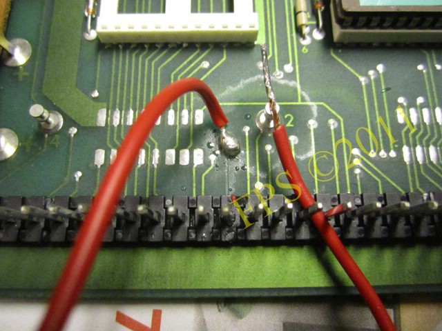
To achieve as good contact as possible between the circuit boards a cable with a "sugar cube" is soldered onto the driver board.
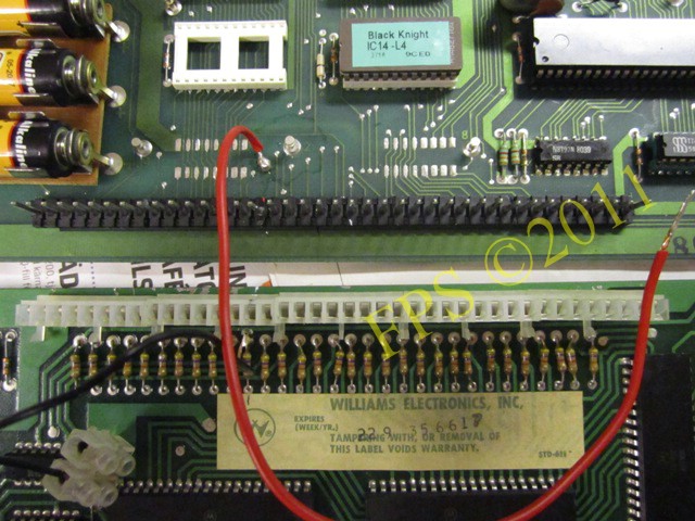
Now, the broken connection are recreated by using a "sugar cube".
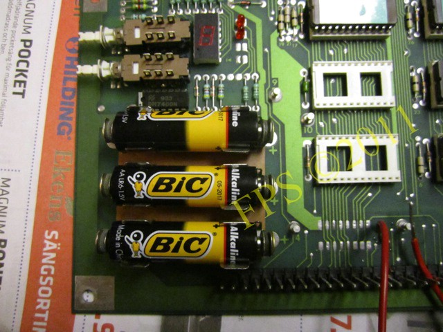
The picture above shows that there is no battery acid on the circuit board from leaking batteries which is good, you have seen boards that have been under great attack from leaking batteries. Often with ruined copper paths (foils) on the circuit board and destroyed IC sockets as result.
CLOSE-UP OF THE BOARDS
 |
 |
 |
 |
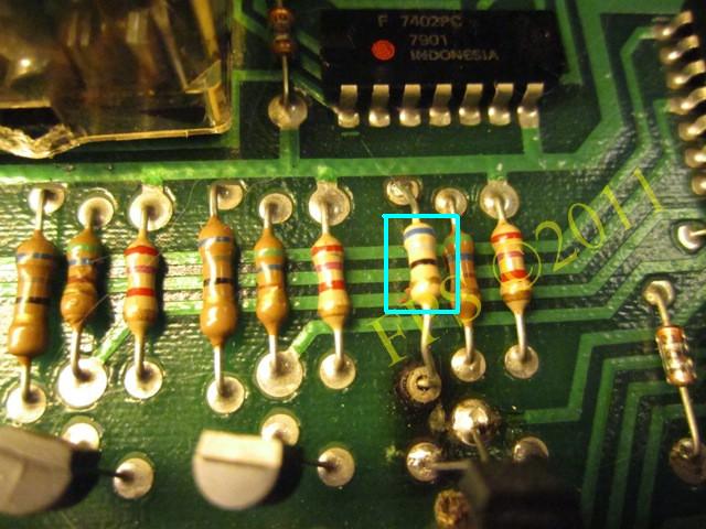
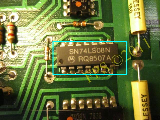
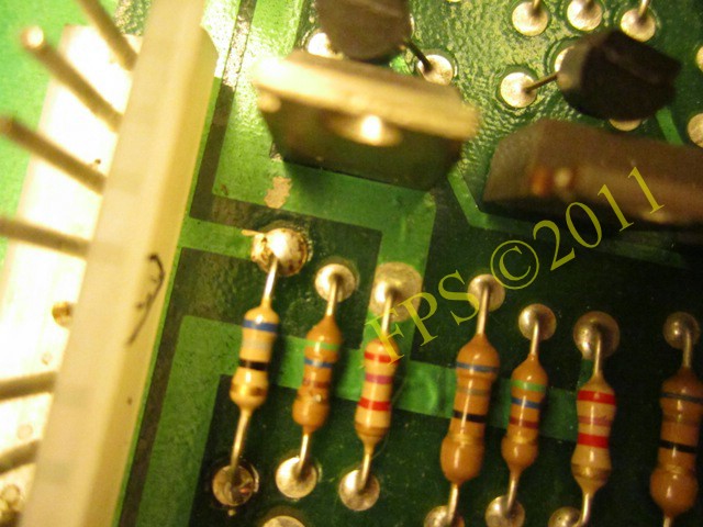
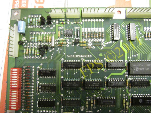
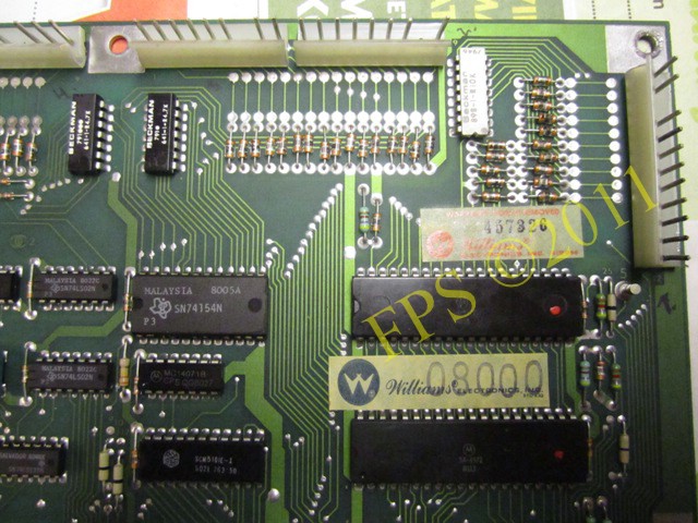
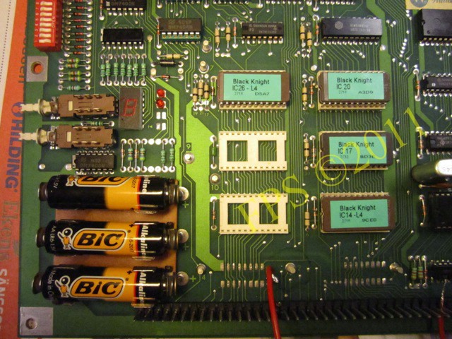
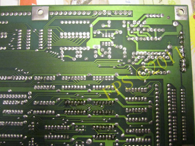
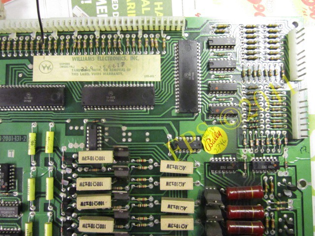
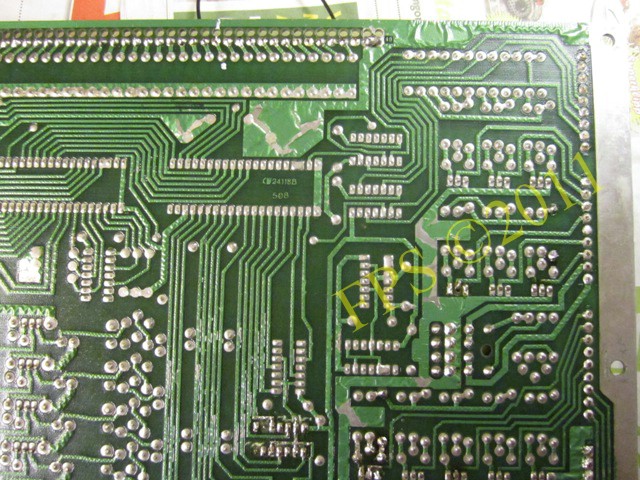
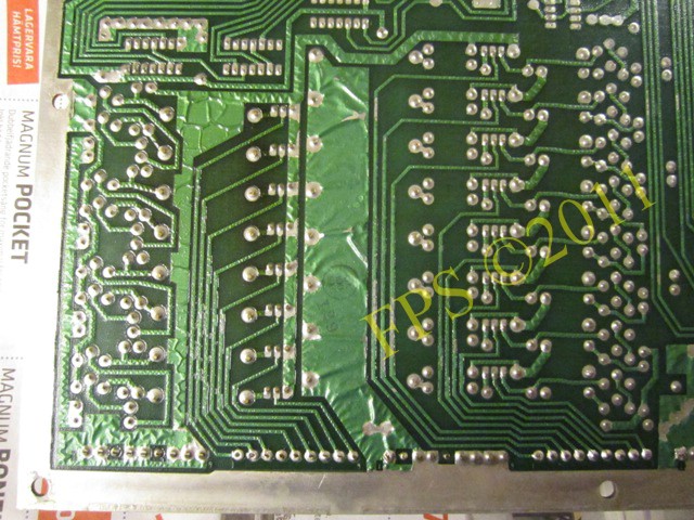
Above pictures of MPU board with its components.
 |
 |
 |
 |
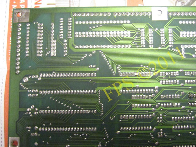
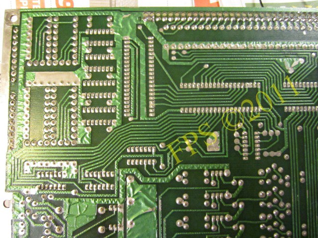
Above pictures on the back of the MPU board with its copper paths (foils).
 |
 |
 |
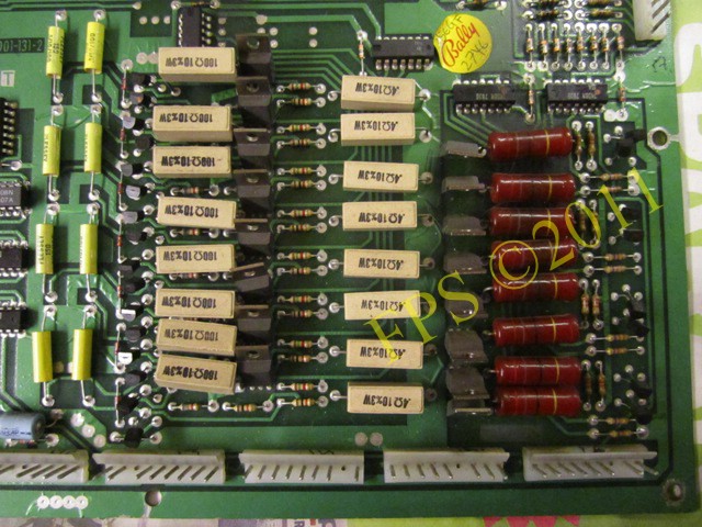 |
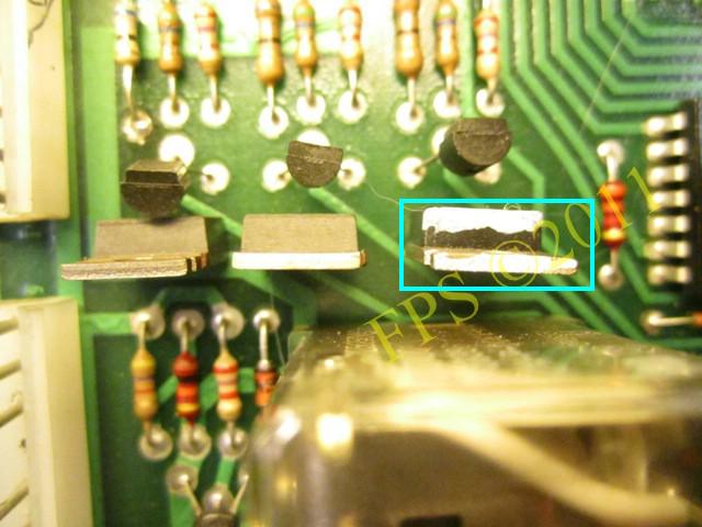
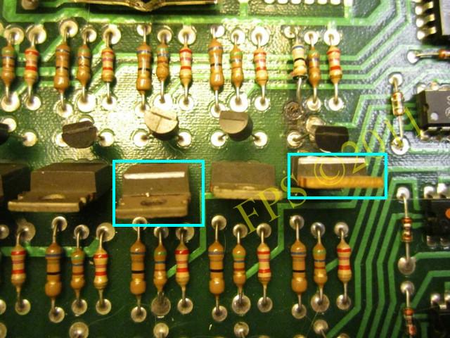
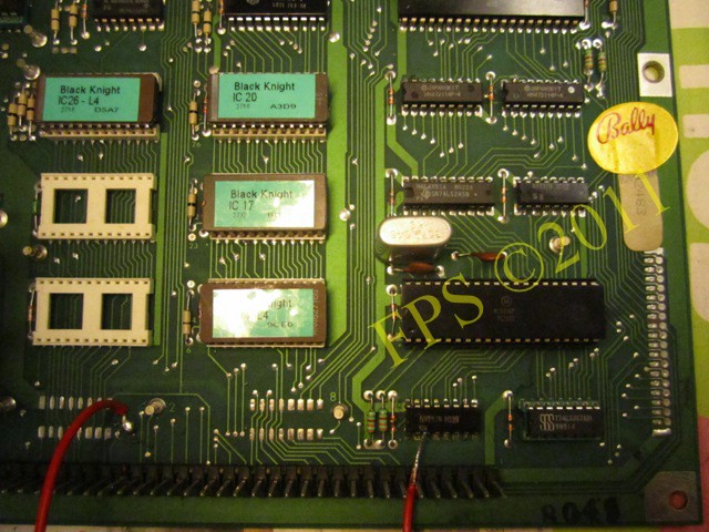
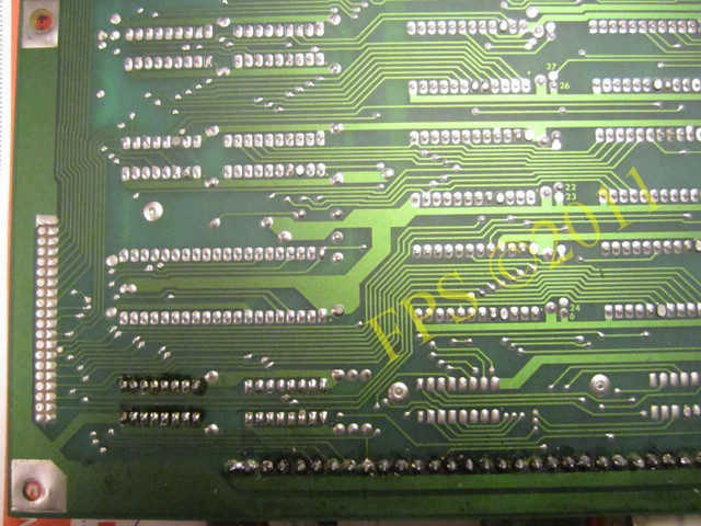
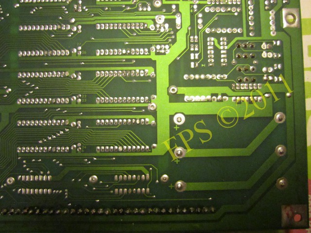
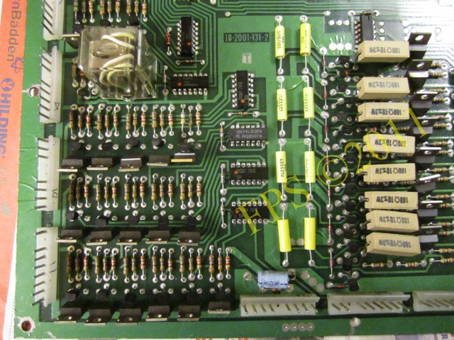
Above pictures on the driver board with its components.
 |
 |
 |
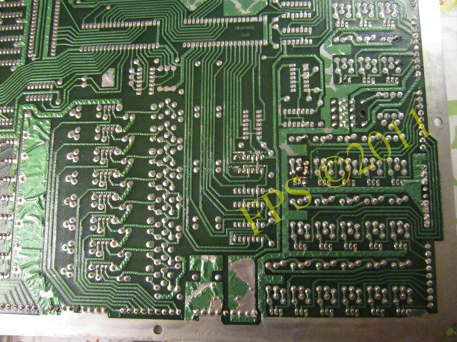 |
Above pictures on the back of the driver board with its copper paths (foils).
NEXT STEP...
Time to try to do a more thorough check of the MPU board outside the pinball machine. There are some points that can be checked on the circuit boards on the workbench. If you connect the +5 V voltage to the circuit board with a power source from a personal computer and have a multimeter and a logical probe pen handy it is possible to do measures on the boards.
Connect +5 V from the power source to contact IJ2, pin 1-3 connection ground (0 V) and 4-6 pin connects +5 V. If the boards works, the two red LEDs will flashing on and then off, indicating that the CPU, clock and reset circuit should be intact.
When switching on the power to mine board the two the red LED's lights constant, so I suspects that something is wrong with CPU or clock and reset circuit.
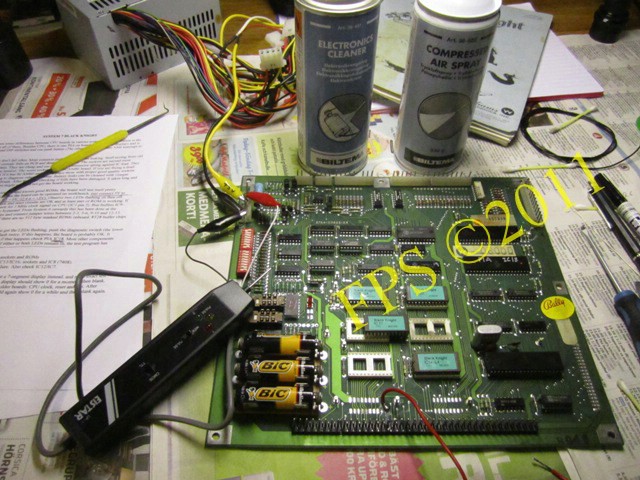
To verify if there is any clock signal I use a logic probe pen by connecting it to IC1 (CPU) pin 3. There is a pulsing signal so I assume that there is a clock signal present.
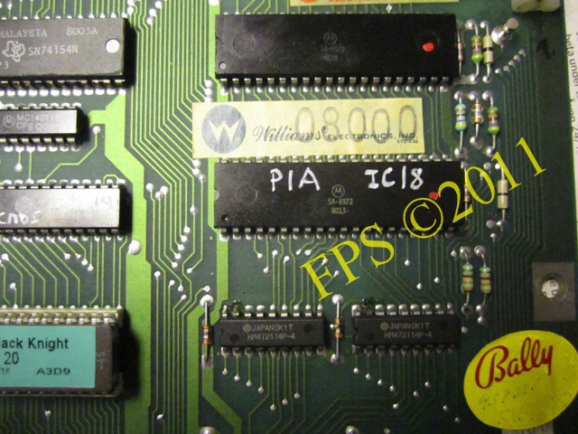
IC18 is the display PIA.
We can see that the IC12, IC32, IC7 has previously been replaced since they have sockets which are not original. Therefore I can assume that the boards struggle with electronic problems since earlier.
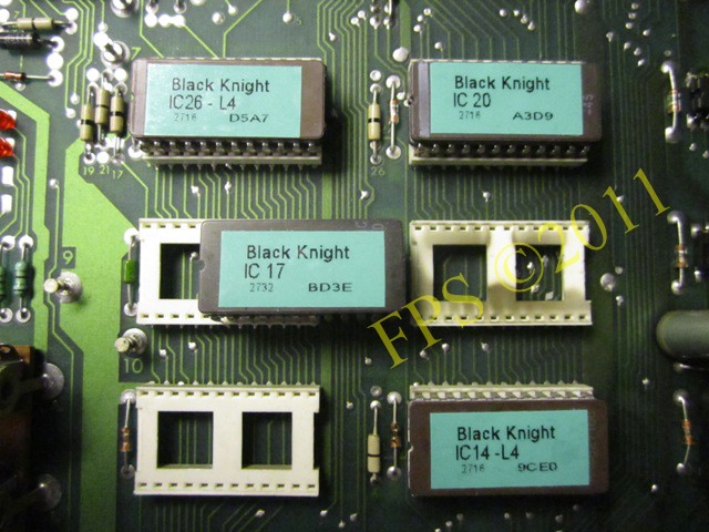
To exclude that there is poor contact between the pins of the ROM circuit (IC216, IC20, IC17, IC14) and its sockets, I carefully remove the ROMs from their sockets and clean the sockets with electronic spray.
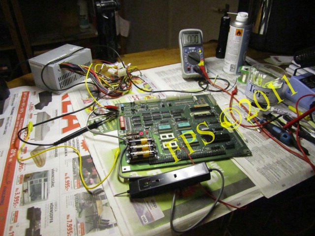
Measurements is done on the MPU board.
In the matrix below, we see which points that I have measured to try to figure out what could be wrong with the board.
| Component | Measure | Set value | Result |
| IC1 (CPU) | PIN 40 | >+4 V | +0.01 V |
| IC1 (CPU) | PIN 8 | +5 V | +4,56 V |
| IC1 (CPU) | PIN 35 | +5 V | +4,57 V |
| IC1 (CPU) | PIN 2 | +5 V | +4,55 V |
| Interboard connector | PIN 37 | +4-5 V | +0.01 V |
The measurement results indicate that there seems to be no blanking signal at pin 37 of the Inter-Board connector so there is a suspicion that there is a problem with IRQ circuit (blanking) which is generated by IC25 (4020). The blanking signal tells the driver board that the CPU has started and then gives a signal to the PIA chips on the driver board that they can provide signals to the solenoids, lamp matrix and displays.
But this is probably not a surprise since the red LEDs already have given an indication that the CPU locks up and does not want to start so I suspect that there is no clock signal to the CPU or the reset circuit does not work.
To prove that the reset circuit is not working can be tested by applying +5 V to IC1 CPU on pin 40, then the CPU shall start without the reset circuit has been active, bridging.If only the reset circuit is the problem, IC1 CPU will now start but this is not happening so there are other problems on the board.
It may be due to a poor crystal (3.58 MHz) so that there is no clock signal to the IC5 (MC6875). If replacing the crystal and no clock signal is still given then we can suspected that IC1 (CPU) is faulty and should be replaced.
THE END...
Components that are replaced on the board to try to get it to work,
Clock circuit |
||
| Crystal | 3.58 MHz | 3.579545 MHz |
| Capacitor | C25 | 27 pF |
| Capacitor | C26 | 27 pF |
Reset krets |
||
| Transistor | Q1 | 2N4403 PNP |
| Transistor | Q2 | 2N4403 PNP |
| Transistor | Q3 | 2N4401 NPN |
| Transistor | Q4 | 2N4401 NPN |
| Transistor | Q5 | 2N4401 NPN |
| Transistor | Q6 | 2N4401 NPN |
| Transistor | Q7 | 2N4401 NPN |
| Transistor | Q8 | 2N4401 NPN |
| Transistor | Q9 | 2N4401 NPN |
| Diode | D19 | 1N4148 |
| Zener diode | ZR1 | 1N5996 6.8 V |
| Zener diode | ZR2 | 1N5990 3.9 V |
THE FINAL SOLUTION...
Pleasure and Pinball
© FPS. All right reserved. |
Page Last updated:
2011-08-12 |