- Home Old school pinball <1985
- Grand Prix (EM) 1976
- Firepower (SS) 1980
- Space Mission (EM)1976
- Genie (SS) 1979
- Magic Castle (SS) 1984
- Black Knight (SS) 1980 New school pinball >1985
- High Speed (Sys11) 1986
- Earthshaker (Sys11) 1989
- CFTBL (WPC) 1992 Arcade Project
- JK-Cabinet with MAME Contents Space Mission
- Playfield Cleaning - Part 1
- Playfield Cleaning - Part 2
- Cabinet Refurbishing
- Backbox Refurbishing
- Refurbishing Diary
- Finsihed project
- Documents - Flyer
|
Language |
|
|
WMS Space Mission Refurbishing project - Part III!
WILLIAMS SPACE MISSION (EM) 1976 - CABINET REFURBISHING
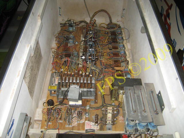
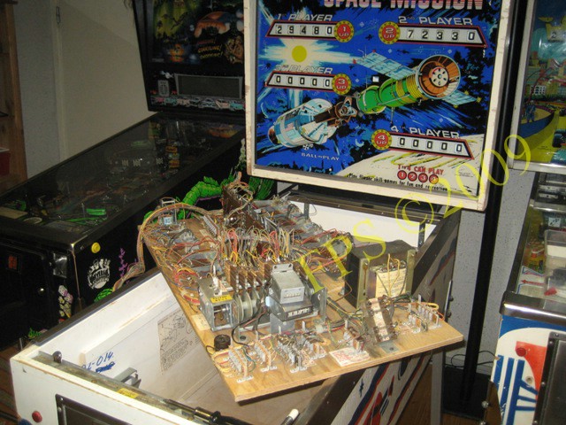
Inside the cabinet on Space Mission.
Here we can see the complete mechanism panel situated in the bottom of the cabinet.
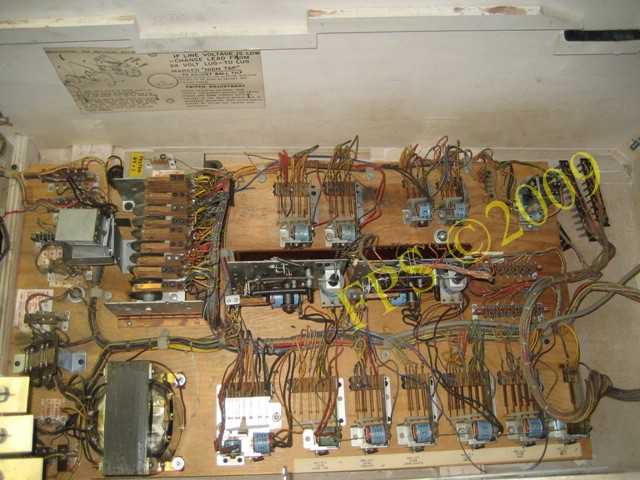
Upper part of the mechanism panel with relays and units.
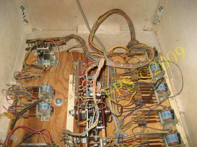
Lower part of the mechanism panel with the Score motor to the left.
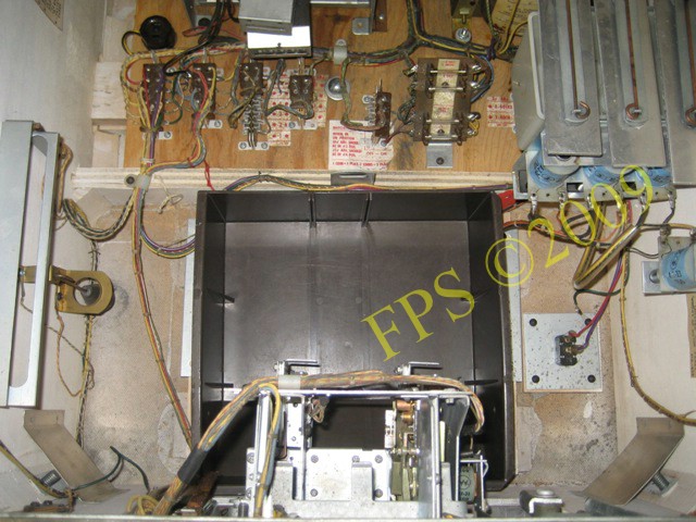
Coin mechanism which is situated in the coin door can be seen in the lower part of the picture and the black box for coins coin box.
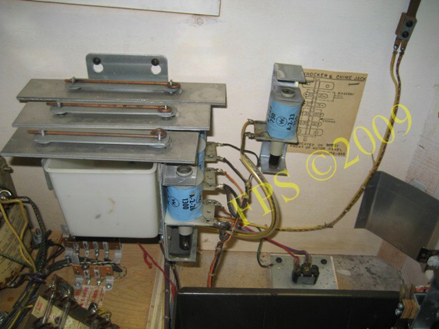
In the picture we see the Chime unit and to the right the knocker.
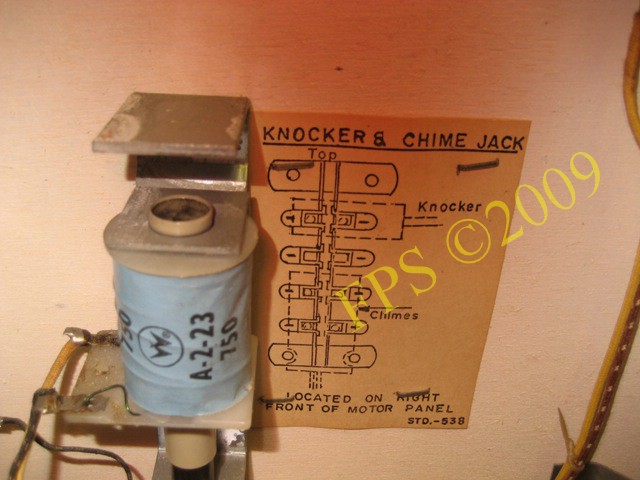
Knocker - who produce a nice sound when a credit is achieved.
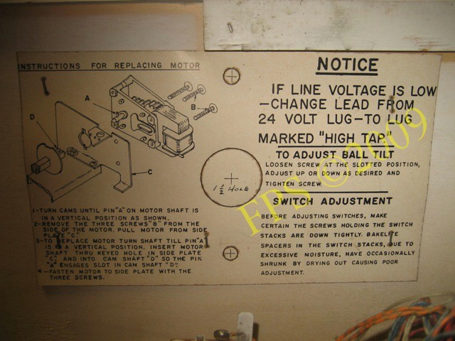
A exploded view of the Swinging target motor on the inside of the cabinet.
MECHANISM PANEL
 |
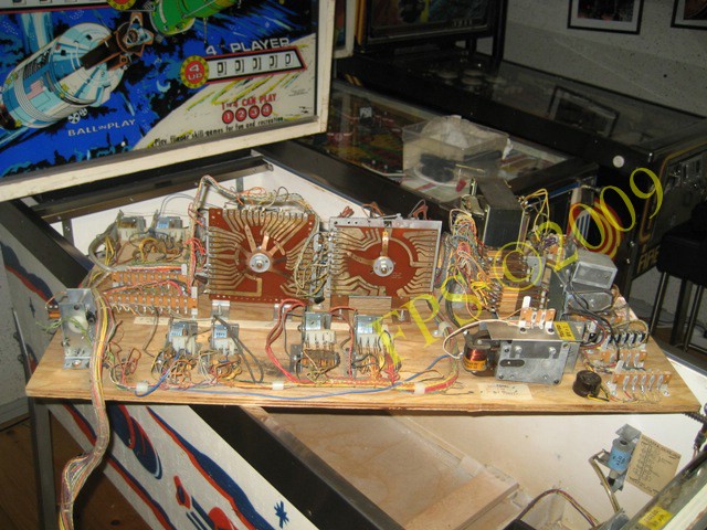 |
I lift up the Mechanism panel and put it on top of the cabinet to facilitate the examination and cleaning of units and relays.
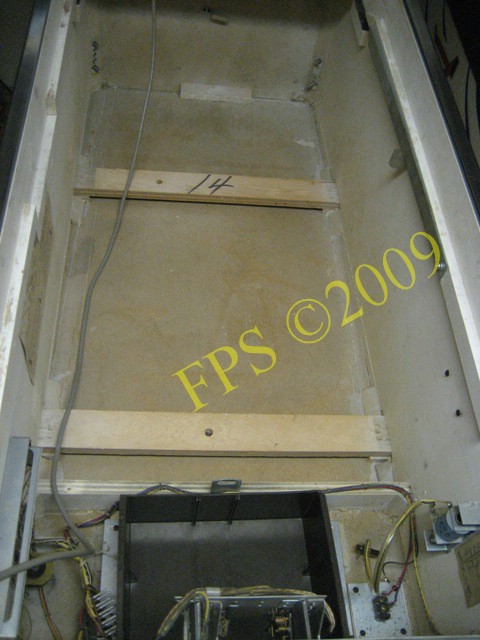
Cabinet with mechanism panel removed.
SCORE MOTOR
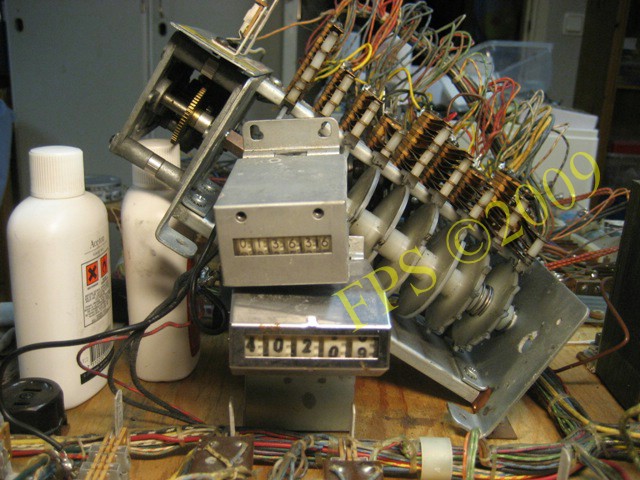
If the two screws is removed on the left end of the score motor it is possible to rise it up and make it easier during the work with the motor - mandatory is to check the adjustment of all your switches on the score motor . The counter "Total play" located in the cabinet showed 40209 plays. The counter above "Cashbox" show 13636 paid coins.
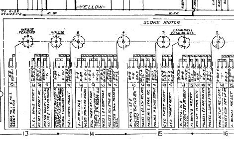
To verify that all switches was correct adjusted "Normally Open" (N.O) and "Normally Closed" (N.C) I made a matrix in excel based on the electrical schema to make it easier to verify each switch. The matrix was also useful when I followed a wire from a switch on the score motor during error seek. The matrix describe each cam with switches in letter order with A closet to the cam, also the wire color code for each switch is in the matrix.
R-W-3 = three wires with color code Red-White. There is a type of switches which consists of both N.C and N.O and they are called Make and Brake M&B. To see the matrix open the picture above.
 |
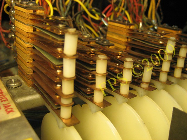 |
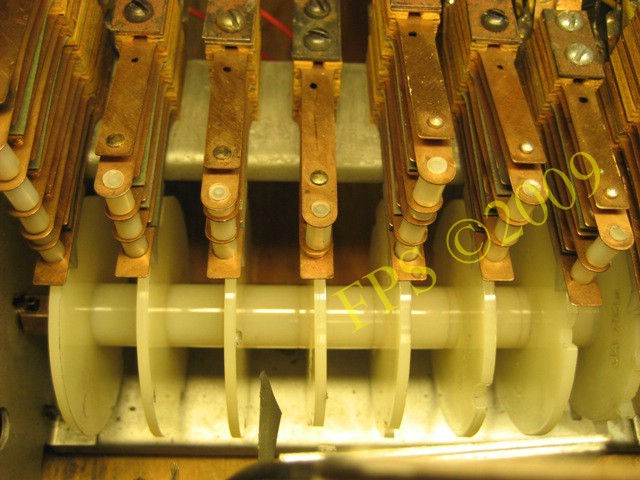
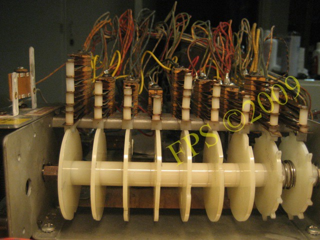
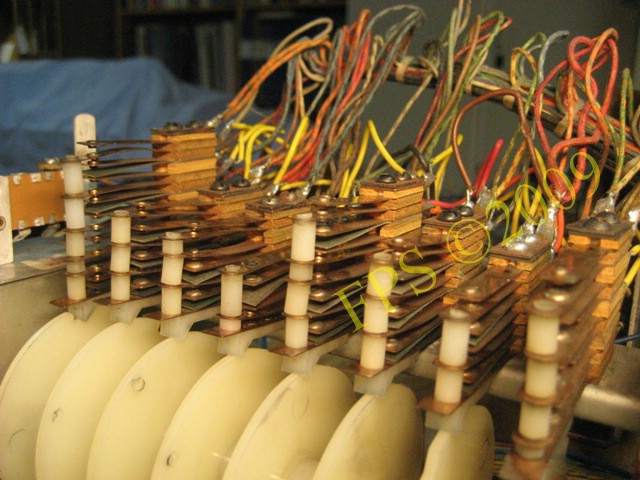
The pictures show the Score motor for Williams Space Mission. Notice all dirt and carbon dust on and around the score motor, especially the stacks of switches is often dirty and oxidized, it is very important that these switches is absolutely clean and correct adjusted to assure the function of the pinball.
The score motor is the pinball's "heart" - it controls almost all functions in a electromechanical pinball. It consists of a electrical motor, axle with notched cams which activates the switches while the axle turns by the motor. The switches is open and closing while the cams is turning.
For example if 5.000 points is scored by hitting a target on the playfield a signal is given by a relay to start the score motor - the score motor makes 5 turns and activate a switch each turn which make a signal to another relay and the score wheel score points - then another switch turn the relay off - simply described.
To mention is that a index cam keep control of the score motors zero/home position.
WARNING- be careful when cleaning and adjust the switches since it is easy to make wrong adjustments or bend a switch during cleaning, continuously use the electrical schematic as reference during the work. During my work with the score motor the classic brain ghost appear and I started to be doubtful about what I had done or not had done during the cleaning/adjustments.
Many problems with older electromechanical pinball's can be related to a dirty or misadjusted score motor.
 |
 |
The adjustment of all switches on the score motor is now verified towards the manual and electrical schematic and also cleaned. For further information about Score motor please visit my project Williams Grand Prix.
DEVICE ON MECHANISM PANEL
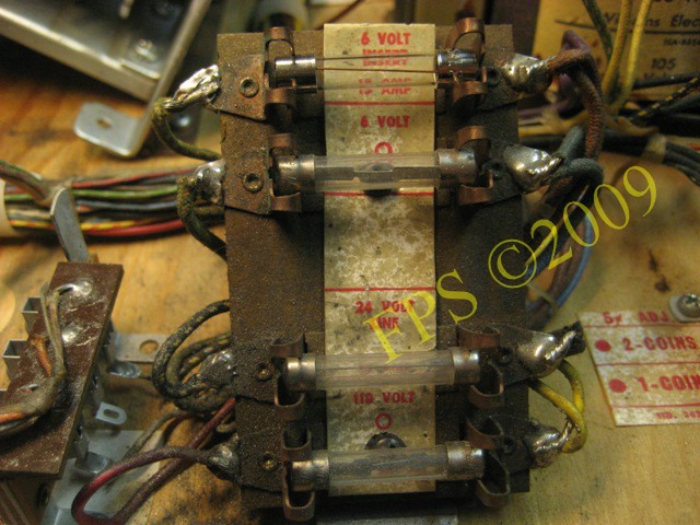
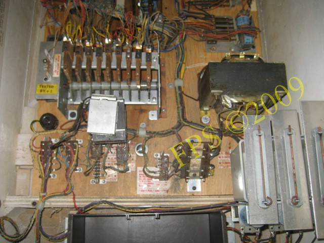
Fuse block. Top are two fuses (15A) for 6 volt G.I. - General Illumination circuits, one for the back box lights and one for the playfield lights. Below these are fuses for 24/110 volt circuits for flippers and solenoids.
 |
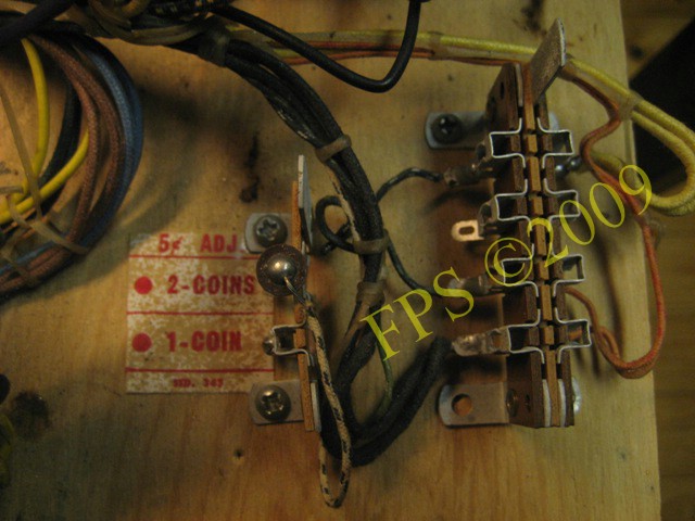 |
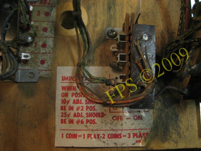
Adjustment for number of credits per coin on Mechanism panel.
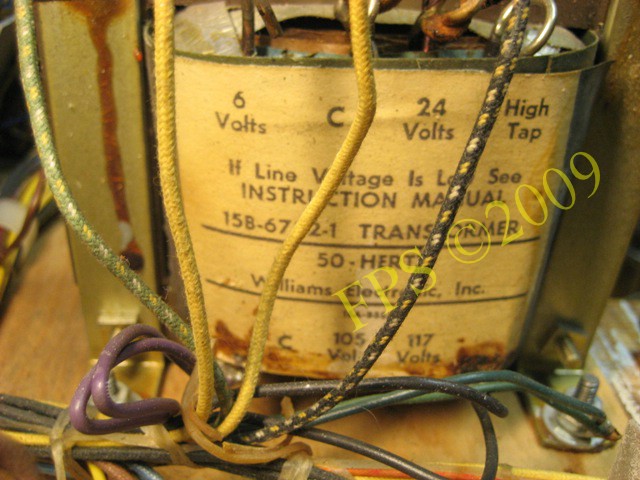
Power transformer 6/24 volt supply for general Illumination (6V) and for flippers and solenoids (24V).
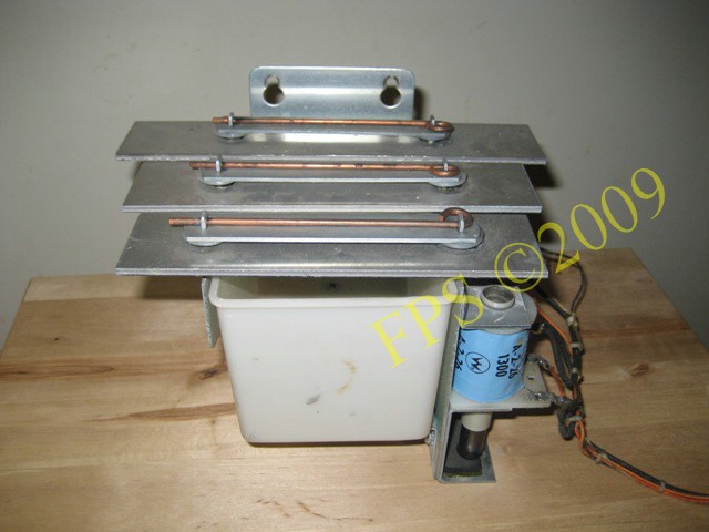
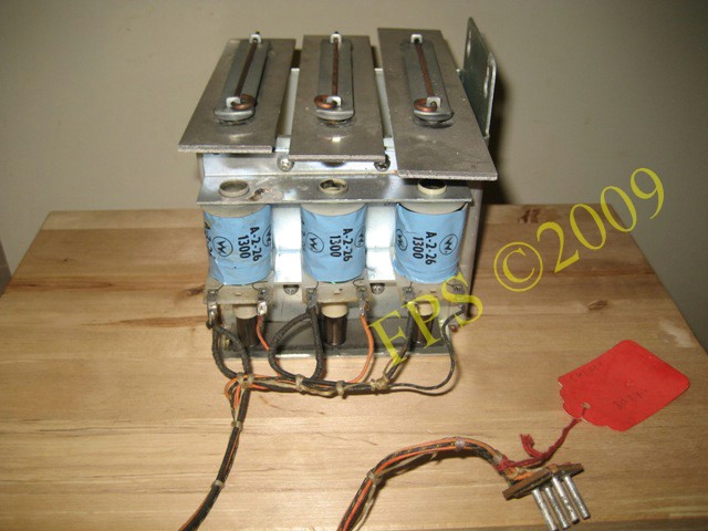
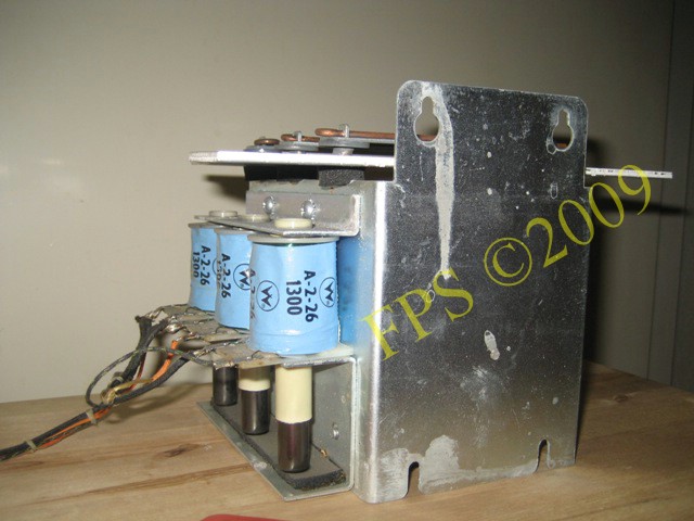
CHIME UNIT
 |
 |
 |
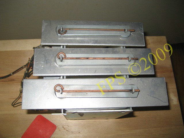 |
Chime unit - that delivers 3 different tones when different points on the playfield is achieved.
Pleasure and Pinball
© FPS. All right reserved. |
Page Last updated:
2009-04-22 |